Industrial facilities run on systems, not on components. A pump, a heat exchanger, a reactor, a storage vessel. None of these operates in isolation. Each one is connected to a piping system that delivers process fluid, removes it, controls pressure, and integrates the vessel into the broader flow of the facility. Pressure vessel fabrication and installation is therefore inseparable from industrial pipe fabrication in the most practical sense: the vessels define the terminal points that the piping connects to, and the quality of the connection between vessel nozzle and piping system determines whether the assembled installation performs reliably or becomes a recurring source of leaks, misalignment, and stress.
For industrial owners and EPCs who manage both scopes simultaneously, understanding how pressure vessel fabrication and installation intersect with piping work, and why coordinating both under a capable partner matters, reduces the risk of the interface problems that so often slow industrial project commissioning.
What Pressure Vessel Fabrication Involves
Pressure vessels are closed containers designed to hold gases or liquids at pressures substantially different from ambient. In industrial settings, they range from small separator vessels in process systems to large reactors and storage tanks that anchor entire production units. Their fabrication is governed by the ASME Boiler and Pressure Vessel Code (BPVC), specifically Section VIII, which establishes the design, material, fabrication, examination, and testing requirements for pressure vessels in most industrial applications.
ASME Section VIII is divided into three divisions of increasing complexity and applicability to different pressure and material conditions. Division 1 governs the vast majority of industrial pressure vessels. Division 2 applies where higher design efficiency is required, typically at higher pressures. Division 3 covers ultra-high pressure applications. Each division requires that vessels be fabricated under a documented quality control program by a manufacturer holding the applicable ASME Code Symbol Stamp, specifically the “U” Stamp for unfired pressure vessels.
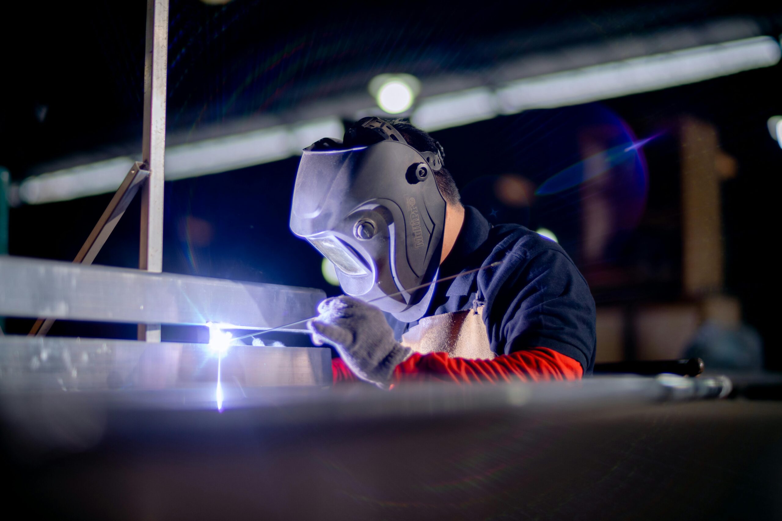
The fabrication process for a pressure vessel involves shell and head forming from plate or rolled sections, nozzle fabrication and attachment, internal fitting installation, welding under qualified procedures by certified welders, in-process examination, post-weld heat treatment where required, hydrostatic testing, and nameplate stamping with the applicable code data.
Our post on Hydrostatic Testing for Industrial Pipe Systems covers the pressure testing procedures and documentation requirements that apply to both piping systems and the vessel hydrostatic test that precedes nameplate stamping, providing context for how testing fits into the broader quality program.
The Nozzle Interface: Where Vessel and Piping Meet
The connection between a pressure vessel and the piping system that serves it occurs at the vessel nozzle. Nozzles are pipe stubs welded through the vessel shell or heads, terminated with a flange or weld-end connection that provides the attachment point for the first piping component outside the vessel.
The design of nozzle connections must accommodate several competing requirements simultaneously. Nozzle loads, the forces and moments imposed by the connecting piping during thermal expansion and operation, must remain within the limits established by the vessel designer. Nozzle orientation and elevation must match the piping layout. Nozzle flange facing and rating must be compatible with the mating piping flange. And nozzle reinforcement must be adequate for the opening cut in the vessel shell.
When the vessel and the piping are designed and fabricated by different organizations without adequate coordination, nozzle orientation errors, flange rating mismatches, and excessive nozzle loads are common findings at installation. A nozzle that is rotated 15 degrees from the drawing orientation forces the piping to be rerouted in the field. A nozzle that cannot accommodate the thermal loads from the connected piping requires a stress analysis revision and potentially a piping redesign.
Our post on How Ansgar Manages Multi-Scope Projects covers how coordinating multiple scopes under a single project team prevents exactly these kinds of interface problems by keeping vessel and piping design synchronized throughout the engineering phase.
ASME Section VIII and the Code Requirements for Pressure Vessel Fabrication
Pressure vessel fabrication and installation in the United States is regulated primarily through ASME Section VIII of the Boiler and Pressure Vessel Code. This code establishes the minimum requirements that must be met for a vessel to receive the ASME Code Symbol Stamp and the National Board registration number that identifies it as a code-compliant vessel throughout its operating life.
Key requirements under ASME Section VIII Division 1 include material specifications from the approved materials list, design calculations demonstrating adequate wall thickness and nozzle reinforcement, welding procedure specifications and procedure qualification records for all welds, welder qualification records confirming that each welder is qualified for the applicable process and position, in-process examination at defined hold points, PWHT for vessel categories and materials requiring it, and hydrostatic testing at 1.3 times the maximum allowable working pressure.
The American Society of Mechanical Engineers (ASME) maintains and publishes the Boiler and Pressure Vessel Code and its applicable interpretations. The code is updated on a two-year cycle, and fabricators must work to the edition and addenda specified in the vessel data report. More information on ASME’s Boiler and Pressure Vessel Code and the U Stamp certification program is available at asme.org.
The National Board of Boiler and Pressure Vessel Inspectors administers the registration system for pressure vessels manufactured under the ASME BPVC. Every pressure vessel that receives a U Stamp must be registered with the National Board by the authorized inspection agency that witnessed its fabrication and testing. The National Board maintains a publicly accessible registry that allows owners, inspectors, and regulatory authorities to verify the registration status of any stamped vessel. More information on the National Board’s registration program and inspection requirements is available at nationalboard.org.
Field Installation: Setting Vessels and Making Final Connections
Pressure vessel fabrication and installation does not end when the vessel leaves the shop. Field installation involves setting the vessel on its foundation, making final piping connections, completing any field welding required at nozzle connections, and verifying that the installed assembly meets the design requirements for alignment, levelness, and nozzle orientation.
Vessel setting requires rigging and heavy lift planning when vessel weight and size exceed the capacity of standard construction equipment. The lift plan must account for the vessel’s weight, center of gravity, and any internals or insulation that contribute to the lift weight. Foundation anchor bolts must be set and grouted before the vessel is set in place, and the vessel must be leveled and aligned to the baseplate within the tolerances specified by the equipment specification.
After setting, the piping connecting to the vessel nozzles is installed and final flange bolting or field weld joints are made. Flanged connections must be made with the specified gasket material, bolting, and torque sequence. Field weld joints at vessel nozzles must be performed under the applicable welding procedure and documented in the piping quality record.
The Occupational Safety and Health Administration (OSHA) establishes requirements for pressure vessel installation under its construction and general industry standards, including requirements for working with pressurized systems, confined space entry for vessel inspection activities, and fall protection during elevated installation work. More information on OSHA’s applicable requirements for pressure vessel installation is available at osha.gov.
How Vessel Installation Affects the Piping Quality Record
When a pressure vessel is installed in a piping system that is itself governed by ASME B31.3 or B31.1, the quality record for the piping system must document how the vessel interfaces with the system. The vessel’s National Board registration number and ASME data report must be referenced in the piping turnover package. Nozzle loads documented in the stress analysis must be filed alongside the piping stress report. Field weld joints at nozzle connections must appear in the piping weld map and weld log.
This documentation chain is not optional on regulated installations. An authorized inspector reviewing the piping system’s turnover package expects to find complete documentation of the vessel-to-piping interface, including confirmation that the vessel was fabricated and stamped to the applicable code, that the nozzle connections were made in accordance with the piping design, and that any field welds at the interface were performed under qualified procedures and examined as required.
Our post on Documentation and Traceability in Pharmaceutical Pipe Fabrication covers the documentation standards that govern regulated piping systems, which extend directly to the pressure vessels connected to those systems and the traceability chain that links vessel certifications to the installed piping record.
Choosing a Partner Who Manages Both Vessel and Piping Scopes
The most effective way to manage the interface between pressure vessel fabrication and installation and the connected piping system is to work with a single partner who understands both disciplines and can coordinate them under a unified quality program and project schedule.
A fabricator who builds both the vessel and the piping connecting to it controls the nozzle orientation from the beginning of the design, coordinates the vessel delivery schedule with the piping installation timeline, and manages the documentation for both scopes under a single quality record system. That integration eliminates the interface gaps that drive field rework when separate contractors discover mismatches at the jobsite.